Students can download Class 10 Science Chapter 12 Electricity Important Questions, KSEEB SSLC Class 10 Science Important Questions and Answers helps you to revise the complete Karnataka State Board Syllabus and score more marks in your examinations.
Karnataka SSLC Class 10 Science Important Questions Chapter 12 Electricity
Question 1.
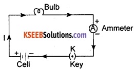
What does an electric circuit mean? Draw a simple electric circuit.
OR
Draw a schematic diagram of an electric circuit.
Answer:
A continuous and closed path of an electric current is called an electric circuit.
Question 2.
When do we say that a circuit is broken or complete? What is the device called that enables us to make or break a circuit?
Answer:
When the conducting path of electric current is complete, we say that the circuit is complete or closed. When the conducting path of electric current is broken somewhere, we say that the circuit is broken or open. The device that enables us to make or break a circuit is called switch.
Question 3.
When do we say that there is an electric current through a circuit?
When electric charges (usually electrons) flow through a conductor (circuit), we say that there is an electric current in it.
![]()
Question 4.
What is the S.I. unit of electric charge? Define it
Answer:
The S.I. unit of electric charge is called ‘coulomb’ (C). 1 coulomb of charge is the charge contained in nearly 6 × 10¹⁸ electrons.
Question 5.
What is the charge on an electron?
Answer:
An electron possesses a negative charge of 1.6 × 10⁻¹⁹ C.
Question 6.
What is electric current? Mention its S.I. unit
Answer:
An orderly flow of electric charges (usually electrons) through a conductor constitutes electric current. The amount of electric charge flowing through a conductor in unit time is called electric current. In other words, the rate of flow of charges through a conductor is called electric current. Consider a conductor through which a charge Q flows in t seconds. Now, the electric current I is given by
Electric current = \(\frac{\text { Quantity of charge flown }}{\text { Time taken }}\)
Current, I = \(\frac{\mathrm{Q}}{\mathrm{t}}\)
The S.I. unit of electric current is called ‘ampere’ (A).
![]()
Question 7.
Define the unit of current.
OR
Define 1 A of current.
Answer:
The unit of current is ampere. When one coulomb charge flows through an electric circuit in one second, then the current flowing through the circuit is said to be one ampere (1 A).
1 ampere = \(\frac{1 \text { coulomb }}{1 \text { second }}\) = 1 Cs-1
∴ 1 A = 1 Cs-1.
Question 8.
Calculate the number of electrons constituting one coulomb of charge.
Answer:
1.6 × 10⁻¹⁹ C of charge is present in 1 electron.
∴ 1 C of charge is present in = ?
No. of electrons present in 1 C of charge = \(\frac{1}{1.6 \times 10^{-19} \mathrm{C}}\)
= 6 × 10¹⁸
Thus, there are 6 × 10¹⁸ electrons in 1 coulomb of charge.
Question 9.
Calculate the amount of charge that flows through a conductor when a current of 5A flows through it for 2 mins.
Answer:
Given, I = 5A, t = 2 min = 2 × 60 s = 120 s, Q = ?
Charge, Q = I × t
= 5 × 120 = 600 C.
Thus the amount of charge flowing through a conductor is 600 C.
Question 10.
A current of 0.5 A is drawn by a filament of an electric bulb for 10 minutes. Find the amount of electric charge that flows through the circuit.
Answer:
Given: Current, I = 0.5 A; Time, t = 10 min = 600 s, Charge, Q = ?
Q = It
= 0.5 A × 600 s = 300 C
Charge of 300 C has flowed through the circuit in 10 minutes.
Question 11.
Name the device used to measure electric current flowing through a circuit.
Answer:
Electric current flowing through a circuit is measured using a device called ammeter.
Question 12.
Name the unit used to express small currents. Give their relationship with ampere.
Answer:
Small currents are expressed using a unit called ‘miiliampere’ or ‘microampere’.
1 miiliampere (1 mA) = 10-3 A
OR
1 microampere (1 pA) = 10-6 A.
![]()
Question 13.
How is an ammeter connected in a circuit?
Answer:
An ammeter is always connected in series in a circuit.
Question 14.
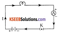
Draw a schematic diagram of a typical electric circuit comprising a cell, an electric bulb, an ammeter and a plug key.
Answer:
Question 15.
In any circuit, state the direction of electric current and the direction of electron current.
Answer:
In any circuit, electric current flows from the positive terminal of the cell towards the negative terminal. Electron current, however, flows from the negative terminal towards the positive terminal of the cell. This means that the direction opposite to the flow of electrons is taken as the direction of conventional current.
Question 16.
Define electrical potential at a point. Give an equation for the same.
Answer:
The electric potential at a point is defined as the work done in moving a unit positive charge from infinity to that point.
If W is the work done in moving a charge Q from infinity to a point, then, the electrical potential V at that point is given by
Electrical potential = \(\frac{\text { Work done }}{\text { Charge moved }}\)
V = \(\frac{\mathrm{W}}{\mathrm{Q}}\)
Question 17.
Define and explain potential difference. Give an equation for the same.
Answer:
Just as liquids flow from a higher level to a lower level, electricity also flows through a conductor from a point of higher electric potential to a point of lower electric potential. This means that a potential difference is necessary for the flow of current through a conductor.
The potential difference between any two points is defined as the work done in moving a unit positive charge from one of those points to the other. It is also called ‘voltage’.
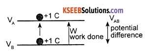
Consider a charge Q moving from point B to point A. Let us say that the work done during the process is W. Let Vbe the potential difference between the two points. Now,
Potential difference = \(\frac{\text { Work done }}{\text { Charge moved }}\)
V = \(\frac{\mathrm{W}}{\mathrm{Q}}\)
![]()
Question 18.
What is the S.I. unit of ‘electric potential’ and ‘potential difference’?
Answer:
Both electrical potential and potential difference are expressed by the same unit namely ‘volt’. It is represented by the symbol V.
Question 19.
Define 1 V of electric potential
Answer:
The electric potential at a point is said to be 1 volt if 1 joule of work is done in moving a charge of positive 1 coulomb from infinity to that point.
1 volt = \(\frac{1 \text { joule }}{1 \text { coulomb }}\)
1 V = 1 JC-1.
Question 20.
Define 1 V of potential difference.
OR
What is meant by saving that the potential difference between two points is 1 V?
Answer:
The potential difference between two points is said to be 1 volt if 1 joule of work is done in moving a charge of +1 C from one of those points to the other.
1 V = \(\frac{1 \text { joule }}{1 \text { coulomb }}\)
1 V = 1 JC-1.
Question 21.
What is the device used to measure the potential difference across a conductor? How is a voltmeter connected in the circuit to measure the potential difference between two points?
OR
Name the device used to measure potential difference across a conductor. How should this device be connected in a circuit?
Answer:
The potential difference across a conductor is measured by using a device called voltmeter. A voltmeter is always connected in parallel in the circuit across the points between which the potential difference is to be measured.
![]()
Question 22.
Name a device that helps to maintain a potential difference across a conductor.
Answer:
We can set up a potential difference by using an electric cell or a battery.
Question 23.
How does an electric cell help to maintain a potential difference across a conductor?
Answer:
The chemical reaction within a cell generates potential difference across the terminals of the cell. When the cell is connected to a circuit, the potential difference sets the charges in motion through the conductor and produces an electric current. The cell maintains the current in the circuit by expending the chemical energy stored in it.
Question 24.
In the circuit given below, the potential difference across the conductor AB is to be measured. Show by a diagram how you would connect a voltmeter to measure the potential difference across AB.

Answer:

A voltmeter should be connected in parallel between the points across which we want to measure the potential difference. Here, we desire to measure the potential difference across AB. The connection of the voltmeter is shown in the circuit diagram given below:
Question 25.
How much work is done in moving a charge of 2 C across two points having a potential difference 12 V?
Answer:
Given: Charge moved, Q = 2 C; Potential difference, V= 12 V; Work done, W = ?
W= VQ
= 12 V × 2 C = 24 J.
Question 26.
The work done in moving 5 C of charge between two points in an electric field is 30 J. Calculate the potential difference between the two points.
Answer:
Given: Charge moved, Q = 5 C, Work done W= 30 J, Potential difference V= ?
V = \(\frac{w}{Q}\)
= \(\frac{30 \mathrm{J}}{5 \mathrm{C}}\) = 6 JC-1
= 6V
![]()
Question 27.
How much energy is given to each coulomb of charge passing through a 6 V battery?
Answer:
Given: Charge moved, Q = 1 C; Potential difference, V = 6 V, Energy given, W = ?
The energy given is nothing but the work done in moving the charge.
W = VQ
= 6V × 1C = 6 J.
The energy given to each coulomb is 6 J.
Question 28.
Name the law that gives the relationship between current flowing through a conductor and the potential difference across it.
Answer:
The law that gives the relationship between current flowing through a conductor and the potential difference across it is Ohm’s law.
Question 29.
State Ohm’s law. Express it in the form of an equation.
Answer:
Ohm’s law states that ‘at constant temperature, the potential difference across a conductor is directly proportional to the current flowing through it’.

Consider a conductor AB. Let V be the potential difference between these points and I be the current flowing through it. Now, according to Ohm’s law,
Potential difference ∝ Current
V ∝ I
V = RI where R is a constant called ‘resistance’ of the conductor.
∴ \(\frac{\mathrm{V}}{\mathrm{I}}\) = Constant.
![]()
Question 30.
What is electrical resistance? Mention its S.I unit.
OR
What is resistance of a conductor?
Answer:
All conductors oppose the flow of electricity through them. The opposition offered by a conductor to the flow of current through it is called its electrical resistance. The S.I unit of electrical resistance is called ‘ohm’. It is represented by the symbol Ω.
Question 31.
Define 1 Ω of resistance.
Answer:
The resistance of a conductor is said to be 1 ? if 1 A of current flows through it when a potential difference of IV is applied across it.
1 Ω = \(\frac{1 \mathrm{V}}{1 \mathrm{A}}\)
1 Ω = 1 VA-1
Question 32.
Draw a simple circuit diagram showing the arrangement of apparatus for the verification of Ohm’s law.
OR
Describe an experiment to show the relationship between potential difference and current.
OR
How do you verify Ohm’s law?
Answer:
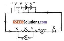
Take an electrical conductor XY made of nichrome. Connect it in series with a battery, a key, a rheostat and an ammeter. Connect a voltmeter parallel to the given resistor. Close the key.
Adjust the rheostat for a small value of current. Note the current and the potential difference by noting down the readings in the ammeter and voltmeter respectively. Go on increasing the value of current in equal but small steps.
Note down the corresponding value of potential difference (V) for each value of current (I). Find the value of V/I in each case. Tabulate the readings as follows:

The value of V/I is found to be a constant. This shows that the potential difference across a conductor is directly proportional to the current flowing through it.
The graph of V against I:
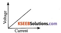
Plot a graph of potential difference against current. The graph of V against I is found to be a straight line passing through the origin. This again shows that the potential difference is directly proportional to the current flowing through it. This verifies Ohm’s law.
![]()
Question 33.
Gowri, while studying the variation of current through a conductor with potential difference, prepared the following table. However, she has left a few blanks in the table. Complete the table using your knowledge of Ohm’s law.
Answer:
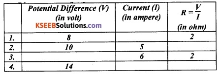
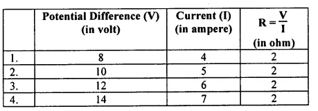
Question 34.
A student measured the potential difference across a nichrome wire for various values of current flowing through it. The values are given in the table below:
Answer:

Draw a graph of potential difference against current. Interpret the graph. Find the value of the nichrome wire used in this activity.
Answer:
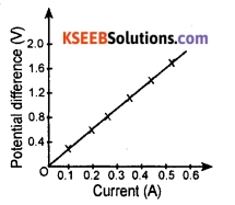
The graph of potential difference (V) against current (I) is a straight line passing through the origin. This shows that the potential difference across the conductor is directly proportional to the current flowing through it.
In other words, the value of \(\frac{\mathrm{V}}{\mathrm{I}}\) is a constant. This constant value is nothing but the resistance of the given nichrome wire.
Resistance, R = \(\frac{\mathrm{V}}{\mathrm{I}}=\frac{0.4 \mathrm{V}}{0.1 \mathrm{A}}\) = 4 Ω.
![]()
Question 35.
Name the device used to provide variable resistance in a circuit.
Answer:
In an electric circuit, a device called rheostat is often used to provide continuously variable resistance. This device can be used to either increase or decrease the resistance of the circuit.
Question 36.
How do you show that the current flowing through an electric component depends upon its resistance?
Answer:
Take a nichrome wire, a torch bulb, a 10 W bulb and an ammeter (0-5 A range), a plug key and some connecting wires. Set up the circuit by connecting four dry cells of 1.5 V each in series with the ammeter leaving a gap XY in the circuit, as shown in the figure below:

Connect the nichrome wire in the gap XY. Close the plug key. Note down the current in the circuit from the reading of the ammeter. Repeat the activity by replacing the nichrome wire with the torch bulb and the 10 W bulb one after the other.
Note down the ammeter reading in each case. Compare the current in the circuit in all the three cases. This is due to the fact that the resistance of each of three gadgets connected in the gap is different. From this we can conclude that the current through an electric component depends on its resistance.
![]()
Question 37.
The values of current I flowing in a given resistor for the corresponding values of potential difference V across the resistor are given below:

Plot a graph between V and I and calculate the resistance of the resistor.
Answer:
If we plot the values of current along the Y-axis and the potential difference (voltage) along X-axis for the values given, we get the following graph:
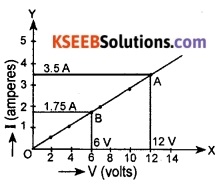
Resistance of resistor (R)
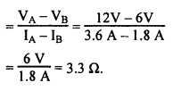
Question 38.
Why does the current flowing through a circuit depend on the resistance of the circuit? How does the current through a device vary with its resistance?
Answer:
Certain components offer an easy path for the flow of electric current while some others resist the flow. We know that motion of electrons in an electric circuit constitutes an electric current.
The electrons, however, are not completely free to move within a conductor. They are restrained by the attraction of the atoms among which they move. Thus, its resistance retards motion of electrons through a conductor. The current flowing through a device is inversely proportional to its resistance.
Question 39.
Let the resistance of an electrical component remain constant while the potential difference across the two ends of the component decreases to half of its former value. What change will occur in the current through it?
Answer:
We know that the current flowing through a conductor is directly proportional to the potential difference across it. Therefore, when the potential difference across the component is reduced to half the initial value, the current will also get halved.
![]()
Question 40.
Distinguish between a good conductor, a resistor, a poor conductor and an insulator on the basis of resistance.
Answer:
A material, which offers low resistance to the flow of electrons or electric current in an electric circuit, is known as a good conductor.
A component in an electric circuit, which offers resistance to the flow of electrons constituting electric current, is known as resistor.
A material, which offers higher resistance to the flow of electrons or electric current in an electric circuit, is known as poor conductor.
A material, which offers very high resistance to the flow of electrons or electric current in an electric circuit, is known as insulator. Electric current does not flow through an insulator.
Question 41.
What potential difference must be applied across a 10 Ω wire in order that a current of 2.5 A flows through it?
Answer:
Given: Current I = 2.5 A; Resistance R= 10 Ω; Potential difference V = ?
V = RI (Ohm’s law)
= 10 Ω × 2.5 A = 25 V.
Question 42.
When a 12 V battery is connected across an unknown resistor, there is a current of 2.5 mA in the circuit. Find the value of the resistance of the resistor.
Answer:
Given: Potential difference, V = 12 V, Current, I = 2.5 mA = 0.0025 A, Resistance, R = ?
According to Ohm’s law, R = \(\frac{v}{1}\)
= \(=\frac{12 \mathrm{V}}{0.0025 \mathrm{A}}\) = 4800 Ω.
Question 43.
- How much current will an electric bulb draw from a 220 V source, if the resistance of the bulb filament is 1200 Ω?
- How much current will an electric heater coil draw from a 220 V source, if the resistance of the heater coil is 100 Ω?
Answer:
1. Given: Voltage, V= 220 V; Resistance, R = 1200 Ω; Current, I = ?

2. Given: Voltage, V= 220 V; Resistance, R = 100 Ω; Current, I = ?

![]()
Question 44.
The potential difference between the terminals of an electric heater is 60 V when it draws a current of 4 A from the source. What current will the heater draw if the potential difference is increased to 120 V?
Answer:
We are given, potential difference V= 60 V, current 7 = 4A.
V 60 V
According to Ohm’s law, R = \(\frac{V}{I}=\frac{60 \mathrm{V}}{4 \mathrm{A}}\) = 15 Ω.
When the potential difference is increased to 120 V the current is given by
Current = \(\frac{V}{R}=\frac{120 \mathrm{V}}{15 \Omega}\) = 8 A.
The current through the heater becomes 8A.
Question 45.
On what factors does the resistance of a conductor depend?
Answer:
The resistance of a conductor depends on the following factors:
- Length of the conductor,
- area of cross-section of the conductor, and
- nature of the material of the conductor.
Question 46.
The resistance of a conductor varies with its length. How do you establish this fact?
Answer:
Take three nichrome wires L1, L2 and L3 of same thickness but of lengths in the ratio 1:2:3 respectively. Complete an electric circuit consisting of a cell, an ammeter, nichrome wire L1 and a plug key, as shown in the figure below.

Now, close the plug key. Note the current in the ammeter. Replace the nichrome wire L1 with nichrome wire L2. Note the ammeter reading. Now replace this wire with nichrome wire L3. Note down the ammeter reading again.
Compare the values of the current through L1, L2 and L3. The current is found to be in the ratio 3:2:1 respectively. This shows that the resistance of L2 and L3 is twice and thrice that of L1 respectively. This establishes that the resistance of a conductor is directly proportional to its length.
Question 47.
How do you show experimentally that the resistance of a conductor varies with its area of cross section?
Answer:
Take three nichrome wires L1, L2 and L3 of same length but of area of cross section in the ratio 1:2:3 respectively. Complete an electric circuit consisting of a cell, an ammeter, nichrome wire L1 and a plug key, as shown in the figure.

Now, close the plug key. Note the current in the ammeter. Replace the nichrome wire L1 with nichrome wire L2. Note the ammeter reading. Now replace this wire with nichrome wire L3.
Note down the ammeter reading again. Compare the values of the current through L1, L2 and L3. The current is found to be in the ratio 1:2:3 respectively.
This shows that the resistance of L2 and L3 is half and one-third that of L1 respectively. This establishes that the resistance of a conductor is inversely proportional to its area of cross section.
![]()
Question 48.
How does the resistance of a wire vary with its area of cross-section?
Answer:
Resistance of a wire is inversely proportional to its area of cross-section. This means that the resistance of a wire decreases in the same ratio as the increase in the area of its cross-section and vice- versa. Thus, if the wire is thick (large area of cross-section), then resistance is less. If the wire is thin (less area of cross-section), then resistance is large.
Question 49.
Will current flow more easily through a thick wire or a thin wire of the same material, when connected to the same source? Why?
Answer:
The resistance of a conductor is inversely proportional to the area of cross-section of the conductor. The current will flow more easily through the thicker wire because the thicker wire has more area of cross-section hence has lesser resistance to the flow of current.
Question 50.
How does the resistance of a conductor vary with (a) its length, and (b) area of cross-section?
Answer:
- The resistance of a conductor is directly proportional to its length.
- The resistance of a conductor is inversely proportional to its area of cross-section.
Question 51.
Explain the factors that affect electrical resistance.
Answer:
1. The electrical resistance of a conductor is directly proportional to its length. This means that the resistance of a conductor increases in the same ratio as the increase in its length.
2. The resistance of a conductor is inversely proportional to its area of cross-section. This implies that the resistance decreases in the same ratio as the increase in its area of cross-section.
3. The resistance of a conductor depends bn its temperature. The resistance of most of the electrical conductors increases with the increase in temperature.
4. Finally, the resistance also depends on the material of the conductor. This means identical conductors made of different materials have different resistances.
![]()
Question 52.
Define ‘electrical resistivity’ of the material of a conductor. Give an expression for the resistivity of a material.
Answer:
The electrical resistivity of the material of a conductor is defined as the resistance of a conductor made of that material of length 1 m and area of cross-section 1 m2.
Consider a conductor of length l and area of cross-section A. Let its resistance be R. We know that the resistance of a conductor is directly proportional to its length t and inversely proportional to its area of cross-section A.

where ρ is a constant called ‘resistivity’ of the material.
Resistivity, ρ = \(\frac{\mathrm{RA}}{l}\).
Question 53.
What is the S.I unit of resistivity? What is the other name for resistivity of a material?
Answer:
The S.I. unit of resistivity is called ‘ohm metre’. Its symbol is ‘Ω. m’. The resistivity of a material is also called its ‘specific electrical resistance’.
Question 54.
You are given three copper wires of length l, 2l and 3l having area of cross-section A, 2A and 3A. Which of these has highest resistivity?
Answer:
Resistivity of a conductor depends only on the material it is made of and not on its dimensions. Therefore, all the three wires have equal resistivity, as all of them are made of the same material namely copper.
Question 55.
A wire of resistivity ? is pulled to double its length. What will be its new resistivity?
Answer:
Since resistivity of a conductor depends only on the material it is made of and not on its dimensions, the resistivity ρ remains the same.
![]()
Question 56.
The electrical resistivity of copper is 1.62 × 10⁻⁸? m. What is the meaning of this statement?
Answer:
The statement above means that a copper wire of length 1 m and area of cross-section 1 m2 has resistance of 1.62 × 10⁻¹⁸ Ω.
Question 57.
The resistivity of some materials is siven in the table below:
| Material | Resistivity (Ω m) |
| 1. Copper | 1.62 x 10⁻⁸ |
| 2. Iron | 10.0 x 10⁻⁸ |
| 3. Mercury | 94.0 x 10⁻⁸ |
| 4. Silver | 1.60 x 10⁻⁸ |
- Which among iron and mercury is a better conductor?
- Which material is the best conductor?
Answer:
- Among iron and mercury, the better conductor is iron. This is because the resistivity of iron is lower than that of mercury.
- Among the given materials, silver is the best conductor of electricity. This is because silver has the lowest value of resistivity.
Question 58.
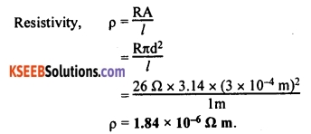
Resistance of a metal wire of length 1 m is 26 Ω at 20°C. If the diameter of the wire is 0.3 mm, what will be the resistivity of the metal at that temperature?
Answer:
Given: Resistance, R = 26 Ω; Diameter, d = 0.3 mm = 3 × 10⁻⁴m, Length of the wire, l = 1 m.
![]()
Question 59.
A wire of given material having length l and area of cross-section A has a resistance of 4 Ω. What would be the resistance of another wire of the same material having length l/2 and area of cross-section 2 A ?
Answer:
For the first wire: R1 = ρ \(\frac{l}{A}\) = 4 Ω
Now for the second wire
R2 = \(\frac{1 / 2}{2 A}=\frac{1}{4} \rho \frac{l}{A}\)
R2 = \(\frac{1}{4}\) R
R1 = 1 Ω.
The resistance of the new wire is 1 Ω.
Question 60.
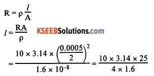
A copper wire has diameter 0.5 mm and resistivity of 1.6 × 10⁻⁸ Ω m. What will be the length of this wire to make its resistance 10 Ω? How much does the resistance change if the diameter is doubled?
Answer:
Area of cross-section of the wire, A = p \(\left(\frac{d}{2}\right)^{2}\)
Diameter = 0.5 mm = 0.0005 m
Resistance, R = 10 Ω
= 122.72 m
∴ Length of the wire = 122.72 m.
If the diameter of the wire is doubled, new diameter = 2 × 0.5 = 1 mm = 0.001 m.
Let new resistance be R’.
R’ = ρ \(\frac{l}{A}\)

= 250.2 × 10-2
= 2.5 Ω
Therefore, the length of the wire is 122.7 m and the new resistance is 2.5 Ω.
Thus, the resistance of the conductor will become \(\frac{1}{4}\) th its initial value when the diameter is doubled.
![]()
Question 61.
Distinguish between resistance and resistivity of a conductor.
Answer:
| Resistance | Resistivity |
| 1. Resistance of a conductor is the obstruction offered by the conductor for the flow of current through it. | Resistivity of a material is the obstruction offered by a conductor of that material of length 1 m and area of cross-section 1 m2. |
| 2. It depends on the material, length and area of cross-section of the conductor. | It does not depend on the length and area of cross-section of the conductor. |
| 3. The S.I. unit of resistance is called ‘ohm’ (Ω). | The S.I. unit of resistivity is called ‘ohm-metre’ (Ωm). |
Question 62.
When do we say that a group of resistances are connected in series? Show by a diagram the arrangement of three resistances in series.
Answer:
A group of resistances are said to be in series if they are connected from end to end so that each of them carries the same current.
Three resistances R1, R2 and R3 are connected in series as shown below:
![]()
Question 63.
Draw the diagram of the electric circuit in which the resistors are connected in series.
OR
Three resistances R1, R2 and R3 are connected in series. This combination is connected in series with a battery, a key and an ammeter. A voltmeter is connected to measure the potential difference across the combination. Draw a suitable circuit diagram for this.
Answer:
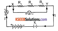
Question 67.
What is the equivalent resistance of a group of resistances connected in series? Give a suitable equation for it.
Answer:
The equivalent resistance of a group of resistances connected in series is equal to the sum of all the individual resistances.
Consider a number of resistances R1, R2, R3………Rn connected in series. Let R be their equivalent resistance. Now,
R = R1 + R2 + R3 + ……… + Rn.
![]()
Question 65.
Obtain an equation for the combined resistance of a group of resistances in series.
Answer:

A group of resistances are said to be in series if they are connected from end to end so that they carry the same current through each of them. Consider three resistances R1, R2 and R3 connected in series.
Let V1 be the potential difference across R1, V2 be the potential difference across R2 and V3 be the potential difference across R3.
Let I be the current flowing through each of these resistors. Let V be the potential difference across the combination and R be the total resistance of the system.
Total potential difference V = V1 + V2 + V3.
But, V = IR, V1 = IR1, V2 = IR2, and V3 = IR3.
Substituting these values in the equation above, we get,
IR = IR1 + IR2 + IR3
∴ Rs = R1 + R2 + R3
This shows that the combined resistance of a group of resistances connected in series is equal to the sum of all the individual resistances in the group.
Question 66.
How do you show that the same current flows through each resistor when a group of resistors are connected in series?
Answer:

Connect three resistors, say of 1 Ω, 2 Ω, 3 Ω, in series. Connect this combination with a battery of say 6 V, an ammeter and a plug key in series. Close the circuit. Note the ammeter reading. Change the position of the ammeter to anywhere in between the resistors and note the reading of the ammeter each time.
Each time the ammeter shows the same current. This shows that, whenever a number of resistors are connected in series, the current flowing through each part of the circuit is same. This is because the current has only one path to flow.
![]()
Question 67.
When do we say that a group of resistances are in parallel arrangement? Show by a diagram the arrangement of three resistances in parallel arrangement.
Answer:
A group of resistances are said to be in parallel arrangement when one end of each resistance is connected to one common terminal and the other end of each resistance is connected to another common terminal. In such an arrangement, the potential difference across each resistance would be the same as all of them have common end points. Three resistances R1, R2 and R3 are connected, as shown below, in parallel arrangement:
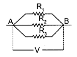
Question 68.
Draw the diagram of the electric circuit in which the resistors R1, R2 and R3 are connected in parallel including ammeter and voltmeter and mark the direction of current.
Answer:
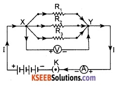
Question 69.
What is the equivalent resistance of a group of resistances connected in parallel? Give a suitable equation for it.
Answer:
The reciprocal of the equivalent resistance of a group of resistances in parallel is equal to the sum of the reciprocals of all the individual resistances.
Consider a number of resistances R1, R2, R3 ……….. Rn connected in parallel. Let R be their equivalent
resistance. Now,

![]()
Question 70.
Obtain an equation for the combined resistance of a group of resistances in parallel
Answer:
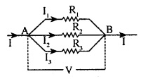
A group of resistances are said to be in parallel if one end of each resistance is connected to one common terminal and the other end is connected to another common terminal so that each resistor has the same potential difference across it.
Consider three resistances R1, R2 and R3 connected in parallel. Let I1 be the current through R1, I2 be the current through R2 and I3 be the current through R3. Let I be the total current through the system, V be the potential difference across each resistor and R be the total resistance of the system.
Total current I = I1 + I2 + I3.
Substituting these values in the equation above, we get,

Thus, the reciprocal of the combined resistance of a group of resistances in parallel is equal to the sum of the reciprocals of all the individual resistances.
Question 71.
Why is the series arrangement not used for domestic circuits?
OR
Mention the disadvantages of connecting electrical appliances in series in domestic wiring.
Answer:
In domestic circuits if gadgets are connected in series, voltage is divided. Each component of a series circuit receives a small voltage so that the amount of current decreases and the device becomes hot and does not work properly.
Secondly, when gadgets are in series arrangement, they cannot be operated independently. If one of them does not work, the circuit is broken and the other components also do not work. Hence, series arrangement is not used in domestic electric circuits.
![]()
Question 72.
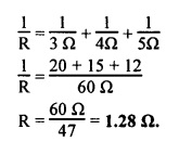
Three resistors of 3 Ω, 4 Ω and 5 Ω are connected in
- series and in
- parallel Find the equivalent resistance in each case.
Answer:
R1 = 3 Ω, R2 = 4 Ω, R3 = 5 Ω, combined resistance R = ?
1. When resistances are connected in series, the equivalent resistance R is given by
R = R1 + R2 + R3
R = 3 Ω + 4 Ω + 5 Ω
= 12 Ω
2. When resistances are in parallel arrangement, the equivalent resistance R is given by
![]()
Question 73.
In the circuit diagram given below, suppose the resistors R1, R2 and R3 have values 5 Ω, 10 Ω, 30 Ω? respectively, which are connected to a battery of 12 V. Calculate
- The current through each resistor,
- The total current in the circuit, and
- The total circuit resistance.
Answer:
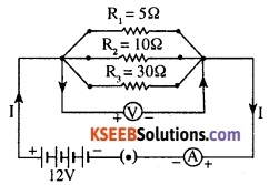
1. Current through 5 Ω resistor = \(\frac{V}{R}=\frac{12 \mathrm{V}}{5 \Omega}\) = 2.4 A
Current through 10 Ω resistor = \(\frac{V}{R}=\frac{12 \mathrm{V}}{10 \Omega}\) = 1.2 A
Current through 30 Ω resistor = \(\frac{V}{R}=\frac{12 \mathrm{V}}{30 \Omega}\) = 0.4 A
2. Total current through the circuit, I = 2.4 A + 1.2 A + 0.4 A = 4 A
3. Total resistance of the circuit, R = \(\frac{V}{I}=\frac{12 \mathrm{V}}{4 \mathrm{A}}\) = 3 Ω.
![]()
Question 74.
If, in the figure given below, R1 = 10 Ω, R2 = 40 Ω, R3 = 30 Ω, R4 = 20 Ω, R5 = 60 Ω, and a 12 V battery is connected to the arrangement Calculate
- The total resistance in the circuit, and
- The total current flowing in the circuit
Answer:
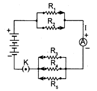
1. Suppose we replace the parallel resistors R1 and R2 by an equivalent resistor of resistance R’ and resistors R3, R4 and R5 by an equivalent single resistor R”. Then,
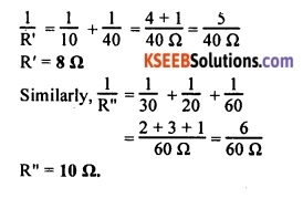
Now, R’ and R” are in series. Let their combined resistance be R. Now, R is the total resistance of the circuit.
R = R’ + R”
R = 8 Ω + 10 Ω = 18 Ω.
2. Current through the circuit, I = \(\frac{V}{R}=\frac{12 \mathrm{V}}{18 \Omega}\) = 0.67 A.
Question 75.
Four resistors 5 Ω, 6 Ω, 4 Ω and 8 Ω are connected in
- series and in
- parallel. Find the equivalent resistance in each case.
Answer:
R1 = 5 Ω, R2 = 6 Ω, R3 = 4 Ω, R4= 8Ω combined resistance R = ?
1. When the resistances are connected in series, the equivalent resistance R is given by
R = R1 + R2 + R3 + R4
R = 5 Ω + 6 Ω + 4 Ω + 8 Ω = 23 Ω.
2. When the resistances are in parallel arrangement, the equivalent resistance R is given by
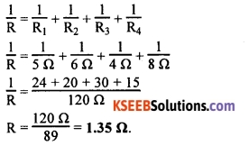
![]()
Question 76.
Why are coils of electric toasters and electric irons made of an alloy rather than a pure metal?
OR
Why are the conductors of electric heating devices, such as bread-toasters and electric irons, made of an alloy rather than a pure metal?
Answer:
Coils of electric toasters and electric irons are made of an alloy rather than a pure metal for the following reasons:
- Alloys have higher resistivity than pure metals. This enables them to generate more heat.
- Alloys, unlike pure metals, generally do not melt easily even at higher temperatures.
Question 77.
Draw a schematic diagram of a circuit consisting of a battery of three cells of 2 V each, a 5 Ω resistor, an 8 Ω resistor, and a 12 Ω resistor, and a plus key, all connected in series.
Answer:

Question 78.
Draw a schematic diagram of a circuit consisting of a battery of three cells of 2 V each, a 5 Ω resistor, an 8 Ω resistor, and a 12 Ω resistor, and a plus key, all connected in series. Put in an ammeter to measure the current through the resistors and a voltmeter to measure the potential difference across the 12 Ω resistor. What would be the readinss in the ammeter and the voltmeter?
Answer:
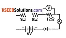
The resistors of 5 Ω, 8 Ω and 12 Ω are connected in series.
The resistance of the circuit = 5 Ω + 8 Ω + 12 Ω = 25 Ω.
Current through the circuit (Ammeter reading) = I = \(\frac{6 \mathrm{V}}{25 \Omega}\) = 0.24 A
Therefore, ammeter reading = 0.24 A.
Voltmeter reading (P.D across 12 Ω) = 12 Ω × 0.24 A = 2.88 V.
Therefore, voltmeter reading = 2.88 V.
![]()
Question 79.
A battery of 9 V is connected in series with resistors of 0.2 Ω, 0.3 Ω, 0.4 Ω, 0.5 Ω and 12 Ω, respectively. How much current would flow through the 12 Ω resistor?
Answer:

Total resistance of the circuit, R = 0.2 Ω + 0.3 Ω + 0.4 Ω + 0.5 Ω + 12 Ω = 13.4 Ω
Current through the 12 Ω resistor, I = \(\frac{V}{R}=\frac{9 V}{13.4 \Omega}\) = 0.67 A
Each resistor in the circuit carries the same current. Therefore, the current flowing through the 12 Ω resistor is 0.67 A.
Question 80.
An electric lamp, whose resistance is 20 Ω, and a conductor of 4 Ω resistance are connected to a 6 V battery as shown in the figure below. Calculate
- The total resistance of the circuit,
- The current through the circuit, and
- The potential difference across the electric lamp and conductor.
Answer:
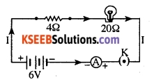
Given: Resistance of the electric lamp, R1 = 20 Ω, Resistance of the conductor connected in series, R2 = 4 Ω, Total resistance of the circuit, R = ?, Current, I = ?, Potential difference across the lamp VL = ?, Potential difference across the 4 Ω resistor = ?
1. The total resistance in the circuit, R = R1 + R2
= 20 Ω + 4 Ω = 24 Ω.
2. Current through the circuit, I = \(\frac{V}{R}=\frac{6 V}{24 \Omega}\) = 0.25 A.
3. Potential difference across the lamp, VL = 20 Ω × 0.25 A = 5 V
Potential difference across the conductor = 4 Ω × 0.25 A = 1 V.
![]()
Question 81.
Judee the equivalent resistance when the following are connected in parallel:
- 1 Ω and 106 Ω.
- 1 Ω, 103 Ω and 106 Ω.
Answer:
1. When 1 Ω and 106 Ω are connected in parallel, the equivalent resistance R is given by:
![]()
2. When 1 Ω, 103 Ω and 106 Ω are connected in parallel, the equivalent resistance R is given by:
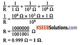
Question 82.
How can three resistors of resistances 2 Ω, 3 Ω, and 6 Ω be connected to give a total resistance of
- 4 Ω
- 1 Ω?
Answer:
1. We must connect 3 Ω and 6 Ω resistors in parallel.
The resulting resistance would be \(=\frac{3 \Omega \times 6 \Omega}{3 \Omega+6 \Omega}\) = 2 Ω
Now, the combination above must be connected in series with the 2 Ω wire.
The resulting resistance would be = 2 Ω + 2 Ω = 4 Ω.

2. To get 1 Ω, we must connect 2 Ω, 3 Ω, and 6 Ω resistors in parallel, as shown below:

Let the combined resistance be R. Now,
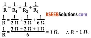
![]()
Question 83.
What is
- The highest,
- The lowest total resistance that can be secured by combinations of four coils of resistance 4 Ω, 8 Ω, 12 Ω, 24 Ω?
Answer:
1. The highest resistance can be secured by combining all the given four resistors in series as shown below:
![]()
The highest total resistance of the system = R1 + R2 + R3 + R4
= 4 Ω + 8 Ω + 12 Ω + 24 Ω
= 48 Ω.
2. The lowest total resistance is secured when the four resistors are in parallel arrangement as shown in the figure below.
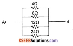
Let the combined resistance be R. Now,


![]()
Question 84.
Show how you would connect three resistors, each of resistance 6 Ω, so that the combination has a resistance of
- 9 Ω,
- 4 Ω.
Answer:
1. Two resistors in parallel and the combination is in series with the third:

Combined resistance of two 6 Ω resistors in parallel = \(\frac{6 \Omega \times 6 \Omega}{6 \Omega+6 \Omega}\) = 3 Ω
When this combination is in series with the other 6 ? resistor, the total resistance = 6 Ω + 3 Ω = 9 Ω.
2. Two resistors in series and the combination in series with the third:

Combined resistance of two 6 ? resistors in series = 6 Ω + 6 Ω = 12 Ω.
When this combination is in parallel with the other 6 Ω,
Total resistance =

Question 85.
How many 176 Ω resistors (in parallel) are required to carry 5 A on a 220 V line?
Answer:
Let the number of 176 Ω resistors required to be connected in parallel to carry 5 A current on a 220 V line be n.

Thus, four resistors of 176 Ω (in parallel) are required to carry 5 A on a 220 V line.
![]()
Question 86.
An electric lamp of 100 ?, a toaster of resistance 50 ?, and a water filter of resistance 500 Ω are connected in parallel to a 220 V source. What is the resistance of an electric iron connected to the same source that takes as much current as all three appliances, and what is the current through it?
Answer:
Given: Resistance of electric lamp, R1 = 100 Ω, Resistance of toaster, R2 = 50 Ω, Resistance of water filter, R3 = 500 Ω, Potential difference of the source, V = 220 V.
Since all the resistances are in parallel, their equivalent resistance R is given by:
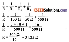
Current drawn by the three appliances, I

The resistance of electric iron which draws same current, R

Therefore, the resistance of the electric iron is 31.25 Ω and the current flowing through it is 7.04 A.
Question 87.
What are the advantages of connecting electrical devices in parallel with the battery instead of connecting them in series?
Answer:
The following are the advantages of connecting electrical devices in parallel with the battery:
- Voltage across each electrical device is same and the device can take current as per its resistance.
- Separate on/off switches can be applied across each device. Hence, they can be operated independent of one another.
- Total resistance in parallel circuit decreases, hence, greater current may be drawn from the cell as per the requirement of the devices.
- Even if one electrical device fuses or fails, the other devices will continue to work.
![]()
Question 88.
Why is it impracticable to connect an electric bulb and an electric heater in series?
Answer:
We have seen that, in a series circuit, the current is constant throughout the electric circuit.
However, gadgets such as an electric bulb and an electric heater need currents of widely different values to operate properly.
This cannot be provided when they are connected in series. Secondly, an electric bulb and an electric heater cannot be operated independently when they are put in series. Therefore, it is impracticable to connect an electric bulb and an electric heater in series. These problems can be overcome by putting these gadgets in parallel connection.
Question 89.
Why is parallel arrangement used in domestic wiring?
OR
It is advantageous to connect electric devices in parallel instead of connecting them in series. Why?
Answer:
In parallel arrangement,
- All gadgets get the same voltage which is equal to the supply voltage itself,
- Gadgets can be operated independent of each other, and
- Even if one of the gadgets goes out of order, the other gadgets will continue to work as the circuit is not broken.
Question 90.
What is meant by heating effect of electric current?
Answer:
When an electric current flows through a conductor, a part of the electrical energy will dissipate in the form of heat. This phenomenon is known as heating effect of electric current.
![]()
Question 91.
Name some devices that work on the principle of heating effect of electric current.
Answer:
Electric heater, electric bulb, electric iron, electric room heater, electric hair drier, electric fuse etc., are some of the devices that work on the principle of heating effect of electric current.
Question 92.
What happens to the power consumed by filament lamps?
Answer:
Most of the power consumed by filament lamps is wasted in the form of heat. A small part of the power appears as light.
Question 93.
What is electric fuse? State the principle on which it works.
Answer:
A safety device provided in electric circuits to protect the circuit and the gadgets from overloading (current exceeding a safe limit) is called an electric fuse. An electric fuse works on the principle of heating effect of electric current.
Question 94.
What is an electric fuse made of? How does it protect electric circuits from overloading?
Answer:
An electric fuse is a short wire made of an alloy of low melting point and low resistance. It is inserted in series in an electric circuit usually inside a porcelain box. When current exceeds the safe limit of the circuit, the heat generated will melt the fuse wire and break the circuit. This is how fuse protects circuits and gadgets in the event of overloading.
![]()
Question 95.
An electric iron consumes 1 kW electric power when operated at 220 V. What is the rating of the fuse wire to be used in the circuit to protect the electric iron from overloading?
Answer:
Given: Power, P = 1 kW = 1000 W; Voltage, V = 220 V; Current, I = ?
Current, I

Therefore, a fuse wire of rating 5 A must be used.
Question 96.
Fuse wire should have higher resistance than the other wires in the circuit but it should not have high melting point. Why?
Answer:
An electric fuse is a device that protects electric circuits from the dangers of overloading. It works on the principle of heating effect of electric current. The fuse wire should have high resistance and low melting point.
This is because its high resistance helps to produce more heat and hence high temperature. Because of its low melting point, the fuse wire melts in the event of overloading and protects the circuit.
![]()
Question 97.
Obtain an expression for the heat produced in a conductor carrying current I and operating under potential difference V.
Answer:
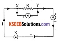
Consider a current 1 flowing through a resistor of resistance R. Let the potential difference across it be V as shown in the figure. Let t be the time during which a charge Q flows across. The work done in moving the charge Q through a potential difference V is VQ. Therefore, the source must supply energy equal to VQ in time t. Hence the power input to the circuit by the source is
P = V \(\frac{Q}{t}\) = VI.
The energy supplied to the circuit by the source in time t, E = P × t.
E = VIt
This energy gets dissipated in the resistor as heat. Thus, for a steady current I, the amount of heat H produced in time t is H = VIt.
But, according to Ohm’s law, V = RI.
∴ H = I2 Rt.
Question 98.
State Joule’s law of heating effect of electric current. Express it in the form of an equation.
OR
According to Joule’s law of heating, mention the factors on which heat produced in a resistor depends. According to this law, write the formula used to calculate the heat produced.
Answer:
According to Joule’s law of heating effect of electric current, the heat generated in a conductor carrying a steady current is directly proportional to:
- The square of the current for a given resistance,
- The resistance of the conductor for a given current, and
- The time for which current flows through the resistor.

Consider a conductor of resistance R carrying current I when the potential difference across it is V.
The heat generated in the conductor in time t second is given by:
H ∝ I2Rt
H = K I2Rt
Here, K is the constant of proportionality. When I is in ampere, R is in ohm, heat produced H is in joule and time t is in second, the value of K becomes equal to 1.
∴ H = I2Rt.
![]()
Question 99.
Compute the heat generated while transferrins 96000 coulomb of charge in one hounthroueh a potential difference of 50 V.
Answer:
Given: Charge transferred, Q = 96000 C; Time, t= 1 hour = 60 × 60 = 3600 s; Potential difference, V= 50 V; Heat generated, H = ?

Heat generated, H = VIt
= 50 V × 26.66 A × 3600 s
= 4800000 J = 4800 kJ
4800 kJ is generated while transferring the charge.
Question 100.
100 J of heat is produced each second in a 4 Ω resistance. Find the potential difference across the resistor.
Answer:
Given: Heat generated, H = 100 J; Resistance, R = 4 Ω, Time, t = 1 s; Potential difference, V = ?
From the equation H = I2Rt we have the current through the resistor as
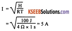
Thus the potential difference across the resistor V is
V=IR
= 5 A × 4 Ω = 20 V.
Question 101.
Why does the cord of an electric heater not slow while the heatine element does?
Answer:
The heating element of the heater is usually made up of alloys, which have very high resistance. Therefore, such heating elements produce high amount of heat and become very hot and glow. The resistance of a conducting cord is usually made of copper or aluminium. These materials have very low resistance. Hence heat produced is also low. Hence they do not glow.
![]()
Question 102.
An electric iron of resistance 20 Ω takes a current of 5 A. Calculate the heat developed in 30 s.
Answer:
Given: Resistance, R = 20 Ω; Current, I = 5 A, Time taken, t = 30 s; Heat generated, H = ?
Heat generated, H = I2Rt
H = (5 A)2 × 20 Ω × 30 s
= 15000J = 15 kJ.
15 kJ heat is developed in 30 s.
Question 103.
An electric heater of resistance 8 Ω draws 15 A from the service mains for 2 hours. Calculate the rate at which heat is developed in the heater.
Answer:
Given, R = 8 Ω, I = 15 A, t = 2h = 7200 s.
Heat generated, H = I2Rt
Rate at which heat is generated, \(\frac{\mathrm{H}}{\mathrm{t}}\) = I2R
= 15 A × 15 A × 8 Ω
= 1800 J.
Question 104.
What determines the rate at which energy is delivered by a current?
Answer:
Electric power determines the rate at which energy is delivered by a current.
Question 105.
Define electric power. Mention its S.I. unit.
Answer:
The rate at which energy is dissipated (consumed) or the rate at which work is done by electric energy is called electric power. It is represented by the letter P.
![]()
The S.I. unit of electric power is called ‘watt’ (W).
![]()
Question 106.
Give an expression for electric power in terms of voltage and current.
Answer:
Electric power is given by the product of voltage and current.
Power = Voltage (Potential difference) × Current P = VI.
Question 107.
Write any two formulae used to calculate electric power.
Answer:
1. Power = Voltage × Resistance
P = VI
2.

Question 108.
Define 1 watt of power.
Answer:
A body is said to have power of 1 watt if it does work at the rate of 1 joule in 1 second. 1 watt of power is the power consumed by a device that carries 1 A of current when operated at a
potential difference of 1 V.
1 watt = \(\frac{1 \mathrm{J}}{1 \mathrm{s}}\) = 1 Js-1.
![]()
Question 109.
What is the commercial unit of electric power? Define it.
Answer:
The commercial unit of electric power is called ‘kilo-watt hour’ (kWh). One kilo-watt hour is the amount of energy consumed by an agent in one hour working at a constant rate of one kilo-watt, i.e., at the rate of 1000 J per second.
Question 110.
An electric bulb is connected to a 220 V generator. The current is 0.50 A. What is the power of the bulb?
Answer:
Given: Voltage, V= 220 V; Current drawn, I = 0.5 A; Power, P = ?
Power, P = VI
= 220 V × 0.50 A
= 110 J/s = 110 W.
Power of the lamp is 110 W.
Question 111.
An electric motor takes 5 A from a 220 V line. Determine the power of the motor and the energy consumed in 2 h.
Answer:
Given: Current, I = 5 A; Voltage, V = 220 V, Time, t = 2 h = 7200 s; Power, P = ?; Energy consumed, E = ?
Electric power, P = VI
P = 220 V × 5 A
= 1100 w
Energy consumed, E = Power × Time
= 1100 × 7200J
= 7920000 J
= 7920 kJ or 7.92 × 10⁶ J.
Question 112.
Two lamps, one rated 100 W at 220 V, and the other 60 W at 220 V, are connected in parallel to electric mains supply. What current is drawn from the line if the supply voltage is 220 V?
Answer:
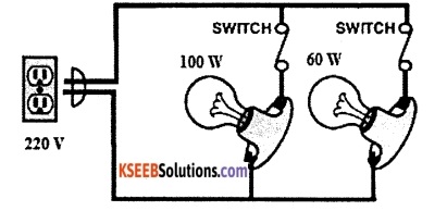
Current, I = \(\frac{P}{V}\)
Current drawn by 100 W lamp = \(\frac{100 \mathrm{W}}{220 \mathrm{V}}\) = 0.45 A.
Current drawn by 60 W lamp = \(\frac{60 \mathrm{W}}{220 \mathrm{V}}\) = 0.27 A.
Total current drawn by the two lamps from the mains = 0.45 A + 0.27 A = 0.72 A.
![]()
Question 113.
Which uses more energy, a 250 W TV set in 1 hour, or a 1200 W toaster in 10 minutes?
Answer:
Energy consumed = Power × Time
Energy consumed by a 250 W television set in 1 hour = 250 W × 3600 s
= 900000 J = 900 kJ
Energy consumed by a 1200 W toaster in 10 minutes = 1200 W × 600 s
= 720000 J = 720 kJ.
Thus, a TV set consumes more energy than the toaster.
Question 114.
A person connects a bulb having resistance 1200 Ω and an electric heater having resistance 100 Ω in series. But they do not work properly. When he connects the same appliances in parallel in the circuit, they function normally. Explain the reason for this.
Answer:
Electrical gadgets of different powers need different currents for their proper functioning. This means the current drawn by an appliance depends on its power. A bulb of 1200 Ω and a heater of 100 Ω cannot work properly when same current flows through each of them.
The bulb needs smaller current while the heater requires larger current. These gadgets can draw the required current from the source only when they are in parallel arrangement. When they are in series, the same current flows through each of them and hence they do not work properly.
![]()
Question 115.
Several electric bulbs designed to be used on a 220 V electric supply line, are rated 10 W. How many lamps can be connected in parallel with each other across the two wires of 220 V line if the maximum allowable current is 5 A?
Answer:
Resistance Ri of the bulb is given by the expression R = \(\frac{V^{2}}{P}\)
Supply voltage, V = 220 V
Maximum allowable current, I = 5 A
Rating of electric bulb P = 10 watts
Given, power = 10W
Potential difference, V= 220 V
Electric current, I = 5 A
To calculate total number of bulbs, total resistance has to be calculated.
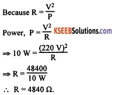
Let the number of bulbs connected in parallel = n.
Let the total effective resistance, when n bulbs are connected in parallel = R1.
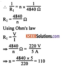
Number of electric bulbs that can be connected in parallel is 110.
Question 116.
An electric iron consumes energy at the rate of 840 W when heating is at the maximum rate and 360 W when the heating is at the minimum. The voltage is 220 V. What are the current and the resistance in each case?
Answer:
Power input, P = VI.
Thus the current I = \(\frac{P}{V}\).
1. When heating is at the maximum rate:
Current, I = \(\frac{840 \mathrm{W}}{220 \mathrm{V}}\) = 3.28 A.
Resistance of the electric iron, R = \(\frac{V}{I}=\frac{220 \mathrm{V}}{3.82 \mathrm{A}}\) = 57.60 ?
2. When heating is at the minimum rate:
Current, I = \(\frac{360 \mathrm{W}}{220 \mathrm{V}}\) = 1.64 A.
Resistance of the electric iron, R = \(\frac{V}{I}=\frac{220 \mathrm{V}}{1.64 \mathrm{A}}\) = 134.15 Ω
![]()
Question 117.
A hot plate of an electric oven connected to a 220 V line has two resistance coils A and B, each of 24 Ω, which may be used separately, in series, or in parallel. What are the currents in the three cases?
Answer:
Given: Potential difference, V=220 V; Resistance of each coil, R = 24 Ω; Current drawn, I = ?
1. When current is drawn separately by the two coils:
Current drawn by each of the coils, I = \(\frac{V}{R}=\frac{220 \mathrm{V}}{24 \Omega}\) = 9.16 A.
2. When the two coils are in series:
Their combined resistance = 24 Ω + 24 Ω = 48
Current drawn by the combination, I = \(\frac{V}{R}=\frac{220 \mathrm{V}}{48 \Omega}\) = 4.58 A.
3. When the two coils are in parallel:
Their combined resistance
![]()
Current drawn by the combination,

Question 118.
Compare the power used in the 2 Ω resistor in each of the following circuits:
- A 6 V battery in series with 1 Ω and 2 Ω resistors, and
- A 4 V battery in parallel with 12 Ω and 2 Ω resistors.
Answer:
1. The circuit shown below has resistance connected in series combination.

Current in the circuit,
![]()
Power used = I2R = (2)2 × 2 = 2 × 2 × 2 = 8W.
2. The circuit is as shown below:
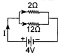
In parallel combination, potential across each resistor is same and equal to the potential applied to the circuit.
Potential across 2 Ω resistor, V = 4 V.
Power used, \(\frac{V^{2}}{R}=\frac{4 \times 4}{2}\) = 8 W.
Power used in both the cases is same.
![]()
Question 119.
What is the commercial unit of energy? Define it. Give its relationship to S.I. unit of power.
Answer:
The commercial unit of energy is called ‘kilo-watt hour’ (kW h).
1 kW h is the energy consumed in one hour at the rate of 1000 joule per second.
1 kilowatt hour = 1 kilowatt × 1 hour
= 1 kW × 1 h
= 1000 W × 1 h
= 1000 J s-1 × 3600 s
1 kW h = 3600000 J = 3600 kJ.
Question 120.
An electric refrigerator rated 400 W is used for 8 hours/day. What is the cost of the energy to operate it for 30 days at Rs 3.00 per kWh?
Answer:
Total energy consumed = Power in watts × No. of hours
= 400 W × 8.0 × 30 days = 96000 W h
= 96 kW h.
The cost of energy = 96 kWh × Rs 3.00 = Rs. 288.00.
Question 121.
An electric refrigerator rated 400 W is used for 8 hours a day. An electric iron box rated 750 W is used for 2 hours a day. Calculate the cost of using these appliances for 30 days, if the cost of 1 kWh is Rs. 3/-.
Answer:
Total energy consumed by the refrigerator in 30 days
= 400 × 8 × 30 = 96000 Wh = 96 kWh
Total energy consumed by the iron box in 30 days
= 750 × 2 × 30 = 45000 Wh = 45 kWh
Total energy consumed by the refrigerator and iron box is
= 96 kWh + 45 kWh = 141 kWh
The bill amount for 141 kWh at the rate of Rs. 3 per 1 kWh is
= 141 × 3 = Rs.423.
![]()
Question 122.
A potential difference of220 V is applied across a resistance of 440 Ω in an electrical appliance. Calculate the current drawn and the heat energy produced in 20 seconds.
Answer:
![]()
Given: V = 220V, R = 440 Ω
Heat energy produced, H = VIt
= 220 × 0.5 × 20 = 2200 J.
Question 123.
Explain the following:
- Why is tungsten used almost exclusively in filament of electric lamps?
- Why are copper and aluminium wires usually employed for electricity transmission?
Answer:
1. Tungsten is a metallic chemical element that has very high melting point and very high resistivity. Therefore, it produces high temperatures but does not melt at such temperatures. It retains as much of heat generated, so that it becomes very hot and emits light. Therefore, it is an ideal material for making filament of lamps.
2. Copper and aluminium are good conductors of electricity and have low resistivity. So, they conduct electric current without heavy heat losses. They are highly ductile. This is why they are usually used for making wires for electricity transmission.
![]()
Fill In The Blanks
1. The rate of flow of charges through a conductor is called current
2. The device used to measure potential difference between two points of a conductor is called voltmeter
3. A device that provides continuously variable resistance is called rheostat
4. The S.I. unit of resistivity of a material is ohm-metre
5. The resistance of a conductor is inversely proportional to its area of cross-section
6. Power of an appliance is given by the product of current and voltage
7. A safety device, which protects circuits from overloading, is electric fuse
8. The commercial unit of electrical energy is called kilo-watt hour
Multiple Choice Questions
Question 1.
A current of 1 A is drawn by a filament of an electric bulb. Number of electrons passing through a cross-section of the filament in 16 seconds would be roughly
(A) 1020
(B) 1016
(C) 1018
(D) 1023
Answer:
(A) 1020
![]()
Question 2.
A piece of wire of resistance R is cut into five equal parts. These parts are then connected in parallel. If the equivalent resistance of this combination is R’, then the ratio R/R’ is
(A) 1/25
(B) 1/5
(C) 5
(D) 25
Answer:
(D) 25
Question 3.
Which of the following terms does not represent electrical power in a circuit?
(A) I2R
(B) IR2
(C) VI
(D) V2/R
Answer:
(B) IR2
Question 4.
An electric bulb is rated 220 V and 100 W. When it is operated on 110 V, the power consumed will be
(A) 100 W
(B) 75 W
(C) 50 W
(D) 25 W
Answer:
(D) 25 W
![]()
Question 5.
Two conducting wires of the same material and of equal lengths and equal diameters are first connected in series and then in parallel in a circuit across the same potential difference. The ratio of heat produced in series and parallel combinations would be
(A) 1:2
(B) 2:1
(C) 1:4
(D) 4:1
Answer:
(C) 1:4
Question 6.
Resistivity of a wire depends on
(A) its length
(B) its material
(C) its cross-section area
(D) All of the above
Answer:
(B) its material
Question 7.
Resistance of a wire is ‘r’ ohm. If the wire is stretched to double its length, then its resistance in ohm is
(A) \(\frac{r}{2}\)
(B) 4 r
(C) r
(D) \(\frac{r}{4}\)
Answer:
(B) 4 r
Question 8.
The unit ‘ampere second’ could be the unit of
(A) power
(B) conductance
(C) energy
(D) electric charge
Answer:
(D) electric charge
![]()
Question 9.
The commercial unit of electrical energy is
(A) kilo-watt
(B) joule
(C) kilo-watt hour
(D) kilo-joule
Answer:
(C) kilo-watt hour
Question 10.
Two resistances R1 and R2 give combined resistance of 4.5 Ω when in series and 1 Ω when in parallel The resistances are
(A) 1.5 Ω and 0.5 Ω
(B) 1.5 Ω and 3 Ω
(C) 2 Ω and 6 Ω
(D) 3 Ω and 9 Ω
Answer:
(B) 1.5 Ω and 3 Ω
Question 11.
The amount of work done in joule, when +1 C of electric charge moves from one point to another point in an electric circuit is called
(A) electric current
(B) electric resistance
(C) electrical resistivity
(D) potential difference
Answer:
(D) potential difference
Question 12.
One kilowatt hour of electrical energy is the same as
(A) 36 × 105 joule
(B) 36 × 105 watt
(C) 36 × 108 watt
(D) 1000 kilo-joule
Answer:
(A) 36 × 105 joule
![]()
Question 13.
Two bulbs marked 200 watt -220 volt and 100 watt -220 volt are joined in series to a 220 volt supply. Power consumed in the circuit is about
(A) 33 watt
(B) 67 watt
(C) 100 watt
(D) 300 watt.
Answer:
(B) 67 watt
Question 14.
The equation form of Ohm’s law is
(A)V = \(\frac{I}{R}\)
(B) R = VI
(C) V = RI
(D) I = VR2
Answer:
(C) V = RI
Question 15.
When a 40 V battery is connected across an unknown resistor, there is a current of 100 mA in the circuit. The value of the resistance is
(A) 5000 Ω
(B) 800 Ω
(C) 0.8 Ω
(D) 400 Ω
Answer:
(D) 400 Ω
![]()
Question 16.
In a circuit, there are two unequal resistances in parallel arrangement. Now,
(A) both resistances carry the same current
(B) higher current flows through higher resistance
(C) potential difference across each resistance is same
(D) the resultant resistance of the circuit increases.
Answer:
(C) potential difference across each resistance is same
Question 17.
The rate of flow of electric charges is called
(A) electric current
(B) electric potential
(C) electrical resistance
(D) resistivity
Answer:
(A) electric current
Question 18.
What is the maximum resistance that can be made using five resistors each of \(\frac{1}{5}\) Ω?
(A) \(\frac{1}{5}\) Ω
(B) 10 Ω
(C) 5 Ω
(D) 1 Ω
Answer:
(D) 1 Ω
Question 19.
Which of the following statements is not true, regarding the circuit set-up for the verification of Ohm’s law?
(A) The voltmeter is connected in parallel with the resistance.
(B) The ammeter is connected in series in the circuit.
(C) Use of a power supply in the circuit is optional.
(D) A single key is used in the electric circuit.
Answer:
(C) Use of a power supply in the circuit is optional.
Question 20.
A cylindrical conductor of length l and uniform area of cross-section A has resistance R. Another conductor of length 21 and resistance R of the same material has area of cross-section equal to
(A) 2 A
(B) \(\frac{\mathrm{A}}{2}\)
(C) \(\frac{3 \mathrm{A}}{2}\)
(D) 3 A
Answer:
(A) 2 A
![]()
Question 21.
Substances that have a large number of free electrons and offer a low resistance are
(A) electrical insulators
(B) good conductors of electricity
(C) materials of high resistivity
(D) poor conductors of electricity
Answer:
(B) good conductors of electricity
Question 22.
Electrical resistivity of a given metallic wire depends upon
(A) its length
(B) its thickness
(C) its shape
(D) nature of the material.
Answer:
(D) nature of the material.
Question 23.
The purpose of a rheostat in a circuit is to
(A) increase the potential difference supplied by the battery
(B) decrease the magnitude of current only
(C) increase or decrease the resistivity of the resistors
(D) change the current in the circuit by changing the resistance
Answer:
(D) change the current in the circuit by changing the resistance
Question 24.
The resistance of a 100 W, 200 V lamp is
(A) 100 Ω
(B) 200 Ω
(C) 400 Ω
(D) 1600 Ω
Answer:
(C) 400 Ω
Question 25.
In an electrical circuit three incandescent bulbs A, B and C of rating 40 W, 60 W and 100 W, respectively are connected in parallel to an electric source. Which of the following is likely to happen regarding their brightness?
(A) Brightness of all the bulbs will be the same.
(B) Brightness of bulb B will be more than that of A.
(C) Brightness of bulb A will be the maximum.
(D) Brightness of bulb C will be less than that of B.
Answer:
(B) Brightness of bulb B will be more than that of A.
Question 26.
The SI unit of electric current is
(A) Ohm
(B) Volt
(C) Ampere
(D) Watt
Answer:
(C) Ampere
![]()
Match The Following
Question 1.
| Column A | Column B |
| 1. Electric current | a. ohm-metre |
| 2. Electric charge | b. coulomb-metre |
| 3. Potential difference | c. ohm |
| 4. Power | d. volt |
| 5. Resistance | e. kilo-watt hour |
| 6. Energy | f. ampere |
| 7. Resistivity | g. coulomb |
| h. watt |
Answer:
1 – f, 2 – g, 3 – d, 4 – h, 5 – c, 6 – e, 7 – a.