Students can Download 2nd PUC Electronics Previous Year Question Paper June 2018, Karnataka 2nd PUC Electronics Question Bank with Answers helps you to revise the complete Karnataka State Board Syllabus and score more marks in your examinations.
Karnataka 2nd PUC Electronics Previous Year Question Paper June 2018
2nd PUC Electronics Previous Year Question Paper June 2018
Time : 3 hrs. 15 min.
Max Marks: 70
Instructions:
- The question has five Parts A, B, C and D.
- Part – A has no choice
- Part – D has two parts. Part -1 is from problems, Part – II is of essay type questions.
- Circuit diagram/timing diagram/truth tables are drawn wherever necessary.
- Problems without necessary formula/formulae carry no marks.
Part – A
Answer all questions: 10 x 1 = 10
Question 1.
Expand JFET.
Answer:
Junction Field Effect Transistor.
Question 2.
Define CMRR.
Answer:
CMRR is the ratio of differential mode gain to common mode gain.
Question 3.
How many frequency components are present in amplitude modulated wave?
Answer:
3
Question 4.
Mention any one application of digital communication system.
Answer:
TV transmission or mobile signal transmission.
Question 5.
Draw the circuit symbol of TRIAC.
Answer:
Question 6.
Write Excess-3 code of (26)10.
Answer:
(26)10 = (010110O1)2
Question 7.
What is a Full-Adder?
Answer:
It is circuit that performs arithmetic sum of 3 binary bits.
Question 8.
Give the meaning of CLR A.
Answer:
Clear the content of Accumulator.
![]()
Question 9.
Write the C-equivalent expression for the mathematical expression
Answer:
(X * Y) / Z
Question 10.
What is Transponder?
Answer:
Transponder is transmitter receiver combination in a satellite.
Part – B
Answer any five questions. 5 x 2 = 10
Question 11.
Define amplification factor. Write its relation with rd and gm.
Answer:
Amplification factor is the ratio of small change in drain to source voltage to the corresponding change in Gate to source voltage for a constant drain current.
ICBO and ICEO
Question 12.
Write the steps involved in drawing AC equivalent circuit of an amplifier.
Answer:
- Reduce all dc sources to zero.
- Short all capacitors.
Question 13.
The open loop gain and closed loop gain of an amplifier are 100 and 50 respectively. Calculate the feedback fraction.
Answer:
Aβ = 100
Af = 50
\(\mathrm{Af}=\frac{\mathrm{A}}{1+\mathrm{A} \beta}\)
β = 0.01
Question 14.
Write any two advantages of negative feedback.
Answer:
- Stabilisation of Gain
- Increase in the bandwidth
![]()
Question 15.
Draw the neat circuit diagram of Wein-bridge oscillator.
Answer:
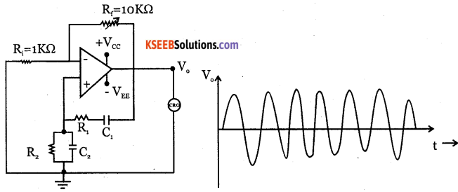
Voltage gain A = \(1+\frac{\mathrm{R}_{3}}{\mathrm{R}_{4}}=3\)
Question 16.
Explain double-injection meahanism in power diode.
Answer:
At higher forward bias, the holes from p+ region reach n~ n+junction and attract electrons from n+ cathode. This leads to electron injection into n~ drift region from n+ cathode layer. This mechanism is called double injection method.
Question 17.
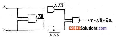
Realize XOR gate using only NAND gates.
Answer:
Question 18.
Mention any two applications of bluetooth.
Answer:
- Wireless communication between PC or laptops or cell phones.
- Used in wireless audio head sets.
Part – C
Answer any five questions. 5 x 3 = 15
Question 19.
What is meant by leakage current? Name two types of leakage currents.
Answer:
The flow of current through the device due to the motion of minority charge carriers under reverse bias condition is called leakage current.
ICBO and ICEO
![]()
Question 20.
What is Ionosphere? Explain F-layer.
Answer:
Ultraviolet radiation from the sun cause the upper atmosphere to ionize i.e. to become electrically charged. Hence a thick layer of ions formed at heights of 50 km to 400km. The ionosphere supports MF and HF wave propagation.
Its three layers are:
D layer: It is at a height of 70 km and has an average thickness of 10 km. It disappears in the night time. It reflects VLF and LF waves and absorbs MF and HF waves.
E layer: It is at a height of 100 km with a thickness of 25 km. This layer disappears at night. It helps in MF and HF wave propagation.
F layer: It is at a height of 150 km and extends upto 400 km. This layer exists during both day and night time. During day time, it splits into two layers F, and F2, and combines to form a single F layer during night time.
| F2 region. 250-400 km. |
| F1 region. 160-250 km. |
| E region. 95-130 km |
| D region. 50-95 km. |
| Troposphere Earth. |
Question 21.
With a neat circuit diagram explain linear diode detector.
Answer:
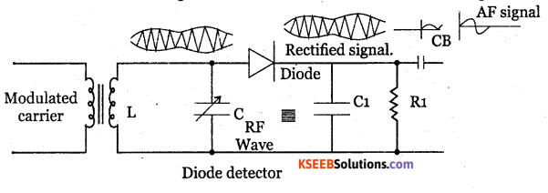
LC tank circuit is used as a parallel resonant circuit. The resonant frequency of the circuit can be varied by varying the value of capacitance C and hence RF signal of any desired frequency can be tuned in.
When a selected modulated signal is applied to the diode, the diode conducts only during the positive half of the modulated wave. Thus the diode removes the entire negative half cycles. Across R1C1 only positive half cycles of carrier modulated wave appears. Thus the low pass filter made up of R1 C1 removes the RF.
During positive half cycle, diode conducts the capacitor C1 gets charged. During negative half cycle of the carrier and diode doesnot conduct but C1 discharges through R1. Hence output is obtained. The spikes can be reduced by proper choice of R1 C1 and depth of modulation. The capacitor CB removes Dc component produced by the detector.
Question 22.
Draw the circuit diagram, gate pluses and load voltage waveform of power inverter.
Answer:

Question 23.
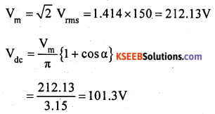
Determine Vdc and Idc of SCR full wave frectifier. Given firing angle is 60°. The rms voltage of ac input to the rectifier is 150V, when load resistance of 15Ω is connected.
Answer:
Question 24.
Name the addressing modes of the following instructions:
(i) MOV R2, A
(ii) MOV A, 25H
(iii) MOV A, @ R0.
Answer:
(i) Register Addressing mode
(ii) Direct Addressing mode
(iii) Indirect Addressing mode
![]()
Question 25.
What is Debugging in C-program? Write the syntax of the if else statement.
Answer:
Debugging is detecting and correcting errors.
if (condition)
{
statement – 1 ;
}
else
{
statement -2;
}
Question 26.
Draw the block diagram of RADAR system and mention the function of duplexer.
Answer:
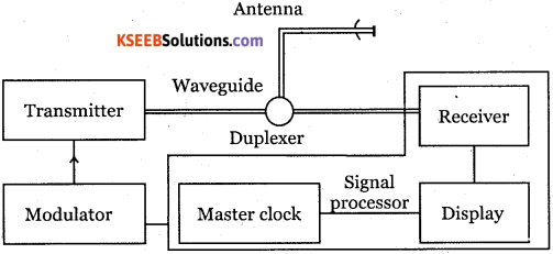
- Transmitter: The radar transmitter produces high-frequency RF pulses and is transmitted into space by the antenna.
- Duplexer: It switches the antenna between transmitter and receiver alternately. This is required because high power pulses of the transmitter will destroy the receiver if energy were allowed to enter the receiver.
- Receiver: It amplifies and demodulates the received RF signals. It provides video signals on the output.
- Radar antenna: The antenna transfers the transmitting signal to space with the required distribution and efficiency.
Part – D
Answer any Three questions: 3 x 5 = 15
Question 27.
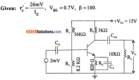
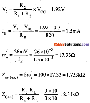
For the CE amplifier circuit shown below, find:
(i) Voltage drop across 8.2 Ω
(ii) IZ
(iii) re
(iv) Zin(base)
(v) Z out
Answer:
![]()
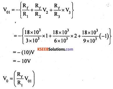
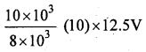
Question 28.
Find the output voltage ‘V0‘ for the following circuit: Given: V1, = IV, V2 = 2V, V3 = -1 V
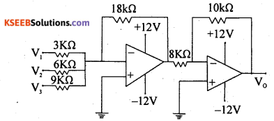
Answer:
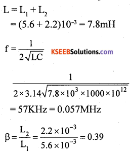
Question 29.
Calculate the frequency and feedback fraction of the circuit shown below:
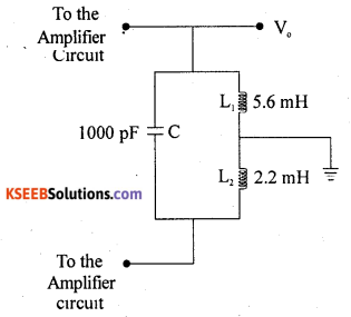
Answer:
Question 30.
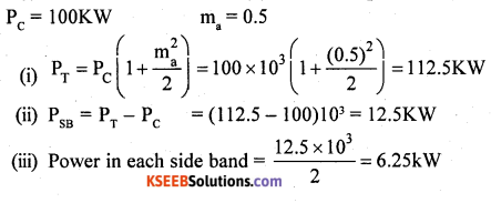
A 100 KW carrier power is amplitude modulated at 50% depth of modulation by a sinusoidal modulating signal. Calculate:
(i) Total power
(ii) Sideband power
(iii) Power in each sideband.
Answer:
Question 31.
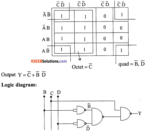
Simplify the following Boolean expression by using K-MAP. If(A, B, C, D) = Σm(0, 1, 2, 4, 5, 8, 9, 10, 12, 13) Draw the logic circuit for the simplified expression using only NAND gates.
Answer:
Part – E
Answer any Four questions. 4 x 5 = 20
Question 32.
Explain with circuit diagram the working of class-B Push-Pull power amplifier.
Answer:
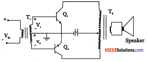
Class B push-pull amplifier is as shown in the diagram. T1 and T2 are two centre tapped transformers and Q1, Q2 are two identical transistors. Transformer T1 produces signal voltages V1 and V2 which are 180° out of phase with each other.
These two signals are applied to the Polarities reverse during negative half cycle of input voltage. Q2then is ON and Q1 is OFF. Q2amplifies the signal and the alternate half cycle appears across the loud speaker.
two transistors. Transformer T2 couples AC output signal from collector to loud speaker. The two emitters are connected to centre tap of transformer T1 secondary and Vcc to the centre tap of T2 secondary.
During positive half cycle of input voltage, secondary winding of T1 has voltages V, and V2. Transistor Q1, conducts and Q2 is cut off. The collector current through Q1 produces an amplified and inverted voltage which applied to loud speaker through a transformer.
![]()
Question 33.
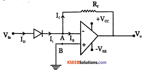
What is a differentiator? With the help of circuit diagram obtain an expression for
output voltage of OP-AMP differentiator.
Answer:
Question 34.
Along with waveforms, derive an expression for instantaneous voltage of frequency modulated wave.
Answer:
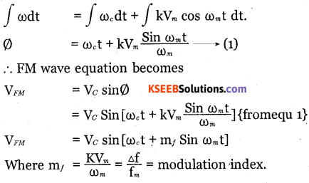
Frequency modulation is the process of varying the frequency of high frequency carrier wave in accordance with instantaneous amplitude of the modulating signal.
Let the modulating signal be given by vm=vm coswt.
Where w is the angular frequency and vm is the peak amplitude. Let the carrier voltage be given by the equation vc= vcsin (Wct +Ø) where wc is the angular frequency of the carrier and Vc is the peak amplitude of the carrier phase angle θ = Wct + θ.
This is instantaneous phase angle of carrier voltage.
Then carrier voltage Vc = Vc sin Ø
The angular frequency \(\omega _{ c }=\frac { d\emptyset }{ dt }\)
or Ø = ∫ ωc dt
The angular frequency of carrier after modulation is
ω = ωc + kvm
ω = ωc + kVmcos ωc t.
Where K is a constant of proportionality called as the modulation deviation constant. On integrating,
Question 35.
Explain the working of four bit synchronous up counter with the help of logic diagram. Write its truth table.
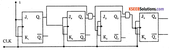
Answer:
Counter is a logic circuit used for counting the pulses. It is a set of flip flops whose state changes in response to pulses applied to their inputs.
Counters are of two types:
- Synchronous counters and
- Asynchronous counters.
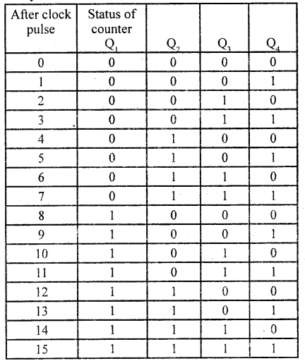
In a synchronous circuit, the clock signal is applied to all flip flops simultaneously.
Question 36.
Write an assembly language program to multiply 08 H and OB H. What are the contents of register A and register B after the execution of the program?
Answer:
MOV A, # 08H → Load the number 08H into the accumulator.
MOV B, # OBH → Load the number OBH into register B.
MOV AB → 08H OBH
08H= 1000(2) 0BH=1011(2)
1000 x 1011 =01011000(2) = 58H
∴ A = 58H B = OOH
![]()
Question 32.
Write a C-program to find the sum of first n
Answer:
# include <stdio.h>
# include < conico.h>
main ( )
{
int n, i, sum = 0;
printf (” Enter the value of n”);
scanf(” % d”, & n);
i= i;
while (i< = n)
{
sum = sum + i; i + +;
}
printf(“The sum = %d”, sum); getch ( );
}